
|
Hangzhou Hengkang Special Vehicle CO.,LTD
|
Product (162)
- Marine Jacks (10)
- A-frame Jacks (8)
- Pipe Mount Jacks (17)
- Bracket Mount Jacks (5)
- Drop-leg jacks (9)
- Electric A-frame Tongue Jacks (4)
- Trailer Jack Accessories (8)
- Ball Mount (16)
- Trailer hitch balls (1)
- Boat Winches (8)
- Air Brake Chamber Series (13)
- Couplers (7)
- Bar locks (2)
- Others (54)
what is trailer jacks (6)
Production Line (2)
News (3)
Other Equipment (2)
Customer Visit (2)
Product Catalog (4)
The Annual Exihibition Attend (4)
Testing Machine (8)
Factory & Workshop Pictures (6)
Company News (1)
Certificates (7)
Credit Report
Products Index
Company Info
Hangzhou Hengkang Special Vehicle CO.,LTD [China (Mainland)]
Business Type:Manufacturer
City: Hangzhou
Province/State: Zhejiang
Country/Region: China (Mainland)
Follow Us:


|
Darcy Lu:
|
what is trailer jacks
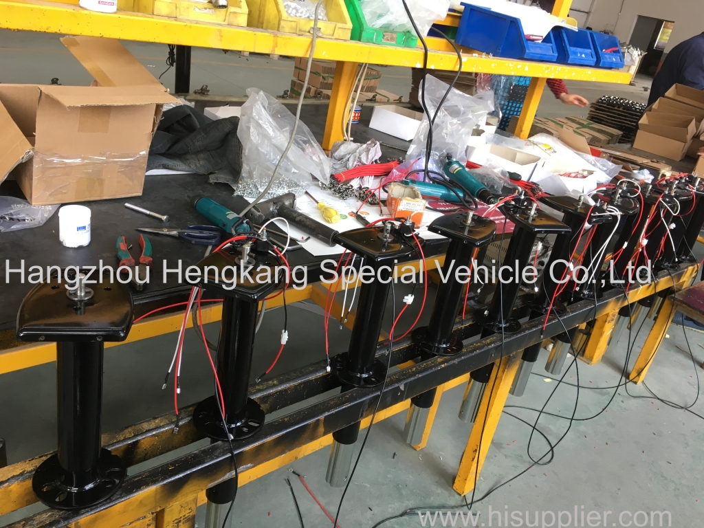
Fig. 1 is a schematic diagram of the decomposition structure of the utility model. Figure 2 for the trailer jack lift state diagram. Figure 3 for the trailer jack down the state diagram.
Implementation method
The present application will now be described in detail with reference to the accompanying drawings. As shown in Figure 1 Figure 1, L a bracket, 2-outer tube, 3-fuel filler, 4 a switch ring, 5-inner tube, 6-screw, 7-bearing, 8- IO-handle cap, 11-nut, 12-opening and closing shaft, B-switch piece, 14-arc surface, 15-opening and closing L, 16-connecting shaft, 17-opening and closing spring, 18-axle, Frame, 20 - tripod liner, 21 - casters, 22 - connecting cap, 23 - limit shoulder. The trailer jack includes an inner cylinder 5 and an outer cylinder 2 arranged outside the inner cylinder. The outer wall of the outer part of the outer cylinder is provided with a fueling nozzle 3 for oil injection. The outer wall of the outer part of the outer cylinder is welded with a bracket 1, The outer cylinder is mounted on the trailer frame, the top end of the inner cylinder 5 is lower than the top end of the outer cylinder 2, the top end of the outer cylinder is semi-closed and the screw hole is left, and the screw 6 is rotatably mounted in the screw hole, And the screw is driven by the screw hole on the bearing and the outer cylinder, and the handle is composed of a connecting cap 22, an "N" type handle rod 9 and a handle cap 10, and the connecting cap Is placed at the top of the screw 6 and connected to the rod by means of a short pin 8. The limit shoulder 23 on the screw and the connecting cap 22 on the handle rod together constitute the axial limit of the screw so that the screw can only rotate and can not move up and down The While the screw 6 is also threaded through the inner cylinder 5 and is threadedly connected to the nut Ll fixed in the inner cylinder, and the manipulating handle drives the screw to rotate the rotational movement of the screw 6 into the upper and lower linear motion of the inner cylinder 5 The The lower portion of the inner barrel 5 extends out of the outer cylinder 2 and is hingedly connected to the trip shaft 19 by means of a connecting shaft 16. The tripod is formed by means of a pair of the same tripod plate 20 and the tripod shaft The axle 18 is provided with a caster 21, and the hinge of the tripod 19 and the inner cylinder 5 can be adjusted to both the raised and the lowered positions, respectively, and a locking stand is provided at the lower portion of the inner cylinder to lift and lower the two states And the opening and closing shaft 12 is inserted into the opening and closing hole 15 which is arranged in the lower portion of the inner cylinder 5, and the opening and closing shaft and the opening and closing hole are both Hexagonal structure to ensure that the opening and closing shaft can only move horizontally in the opening and closing hole, the opening and closing shaft 12 has an inner shoulder, and an opening and closing spring 17 is arranged between the inner shoulder and the inner wall of the inner cylinder. The spring is in the normal state Is always in a compressed state to keep the opening and closing shaft 12 extending from the opening and closing hole 15 of the inner cylinder 5-side from the other side of the inner recess and to extend the projecting end against the tripod The switch plate 4 is provided with the opening and closing of the locking mechanism, and the contact surface of the switch piece is the structure of the arc surface 14 to facilitate opening, and the trailer jack has Two state positions, shown in Figure 2 shows the state of the lift position, the operation is to manipulate the handle cap IO clockwise shaking, through the handle rod 9 to drive the screw 6 rotation, the screw rotation movement into the inner tube 5 upward linear motion , The switch piece provided on the inner cylinder is gradually brought into contact with the switch coil 4 at the lower end of the outer cylinder during the rise of the inner cylinder, and the opening / closing shaft 12 is actuated to overcome the spring force of the opening and closing spring 17 on the opening and closing shaft The opening and closing shaft is moved horizontally outwardly, and at this time, the opening and closing shaft is disengaged from the tripod liner 20 so that the leg 19 can be lifted up and down around the lower end of the inner cylinder 5, and the handle cap IO is continuously moved The lower switch ring 4 is fastened to the tripod 19 and the open-off switch piece 13 is also fastened to the caster 21 so that the entire tripod 9 is in the raised position where the trailer can be Tractor towing. 3 is a schematic view of a state of lowering the state in which the operation of the handle cap 10 is rotated by the handlebar 9 to rotate the screw 6 and the rotational movement of the screw is converted into a downward movement of the inner cylinder 5, In the descending process, the switch plate provided on the inner cylinder is gradually disengaged from the switch ring at the lower end of the outer cylinder so that the opening and closing shaft moves horizontally inwardly by the closing spring 17 of the opening and closing shaft 12, At the same time, the entire tripod also rotates about the inner cylinder 5, and when the opening and closing shaft is extended into the tripod liner 20, the entire trip frame is returned to the lowered position position, since the opening and closing shaft 12 The tripod 19 does not return to the raised position where the trailer is disconnected from the tractor and can be parked in a stable manner, compared with the existing trailer jack, The height of the lower position is higher, so it can raise the height. The utility model can be applied to agricultural trailers for loading goods or used in towing cars, and can also be applied to trailers loaded with yachts, and can be made according to different use of different sizes, the use of a wider range, the use of flexible , Convenient, effort.
(6) mounted on a trailer and an inner cylinder (5) provided in the outer cylinder and lower than the top of the outer cylinder, a screw (6) rotatably connected to the top of the outer cylinder, (11) is threadedly connected with the nut (11) fixed in the inner cylinder, the handle is fixed at the tip of the screw and is transformed into the upper and lower linear motion of the inner cylinder by the rotational movement of the screw (6), and the upper part of the outer cylinder and the screw (21), and a caster (21) is mounted on the tripod, characterized in that the tripod (19) is provided with a support (7) (5) is provided at the lower end of the inner cylinder (5). The lower end of the inner cylinder (5) is further provided with a lock mechanism (19) for lifting and lowering the two position positions, (12), the opening and closing shaft through the inner cylinder opening and closing hole (15) and the tripod liner (20) constitute the rotation limit of the tripod (19), and the inner and the inner cylinder (2) is provided with a opening and closing spring (17), and the lower part of the outer cylinder (2) is provided with a switch ring (4), and the switch ring and the switch piece (13) constitute opening and closing of the locking mechanism.
2. A trailer jack according to claim 1, characterized in that the outer wall of said outer cylinder (2) is provided with a fuel filler (3) which is welded to the outer wall of the lower part of the outer cylinder (2) Of the stent (1).
3. A trailer jack according to claim 1, characterized in that said opening and closing shaft (12) is a polygonal shaft and the opening and closing hole (15) fitted therewith is a polygonal hole.
4. A trailer jack according to any one of claims 1 to 3, characterized in that the contact surface of said switch piece (13) and the outer tube switch ring (4) is in the form of an arc (14).
Abstract: A trailer jack can support the trailer when the trailer and the tractor disengage, and its structure includes outer cylinder, inner cylinder, screw, handle, nut, bearing, tripod and casters, etc., and the screw The main function is to hinge the tripod at the lower end of the inner cylinder, and at the lower end of the inner cylinder with a locking stand to lift and put down the two state position of the locking mechanism, the improved after the The structure of the use of more flexible and convenient, tractor towers will be lifted when the tripod, the two will be released when the tripod down support, so regardless of the tractor and trailer are not connected in the state do not have to remove the trailer jack, More loading time, to overcome the use of trouble and time-consuming and laborious defects, with a higher height to meet the functional needs.
